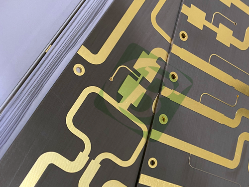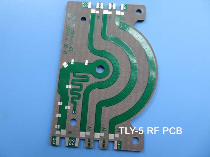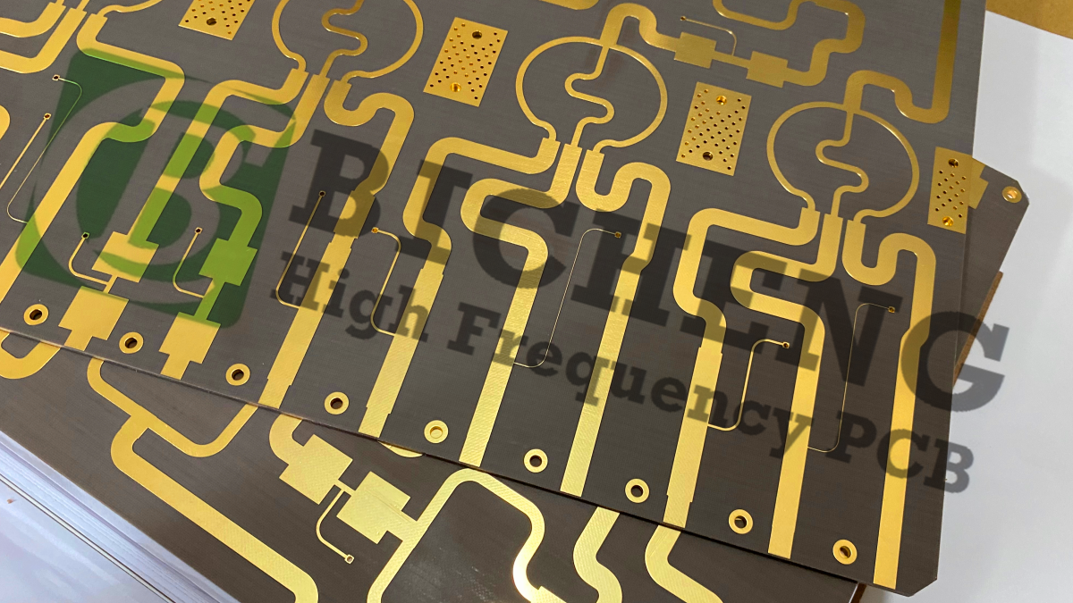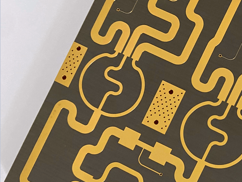
TLY-5 2-Layer 10mil High-Frequency Thin PCB with Immersion Gold1.Introduction TLY-5 laminates are manufactured with very lightweight woven fiberglass and are much more dimensionally stable than chopped fiber reinforced PTFE composites. The woven matrix in the TLY-5 material yields a more mechanically stable laminate that is suitable for high volume manufacturing. The low dissipation factor enables successful deployment for automotive radar applications designed at 77 GHz as well as other antennas in millimeter wave frequencies. 2.Key Features Dielectric constant of 2.2 with tight tolerance 0.02 at 10 GHz/23°C 3.Benefits Dimensionally stable
4.PCB Construction Details
5.PCB Stackup (2-Layer Rigid Structure) Copper layer 1 – 35 µm 6.PCB Statistics: Components: 9 7.Typical Applications Automotive Radar 8.Quality Assurance Artwork Format: Gerber RS-274-X |
Get a Quick Quote
Fill in the form below and our engineers will reply within 24 hours with technical specifications and pricing for TLY-5 2-Layer 10mil Thin PCB.
.jpg)
.jpg)